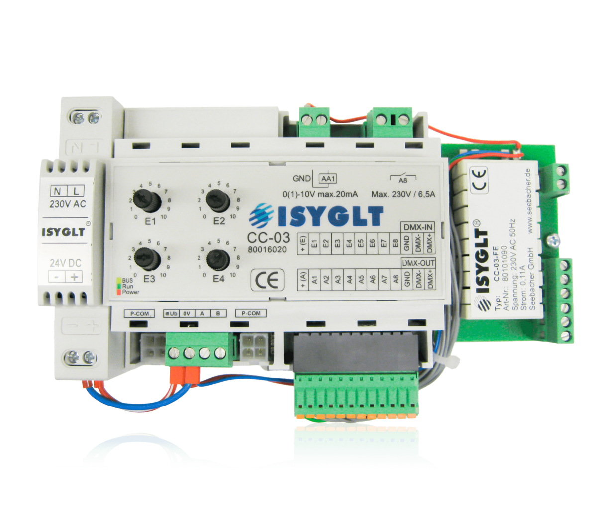

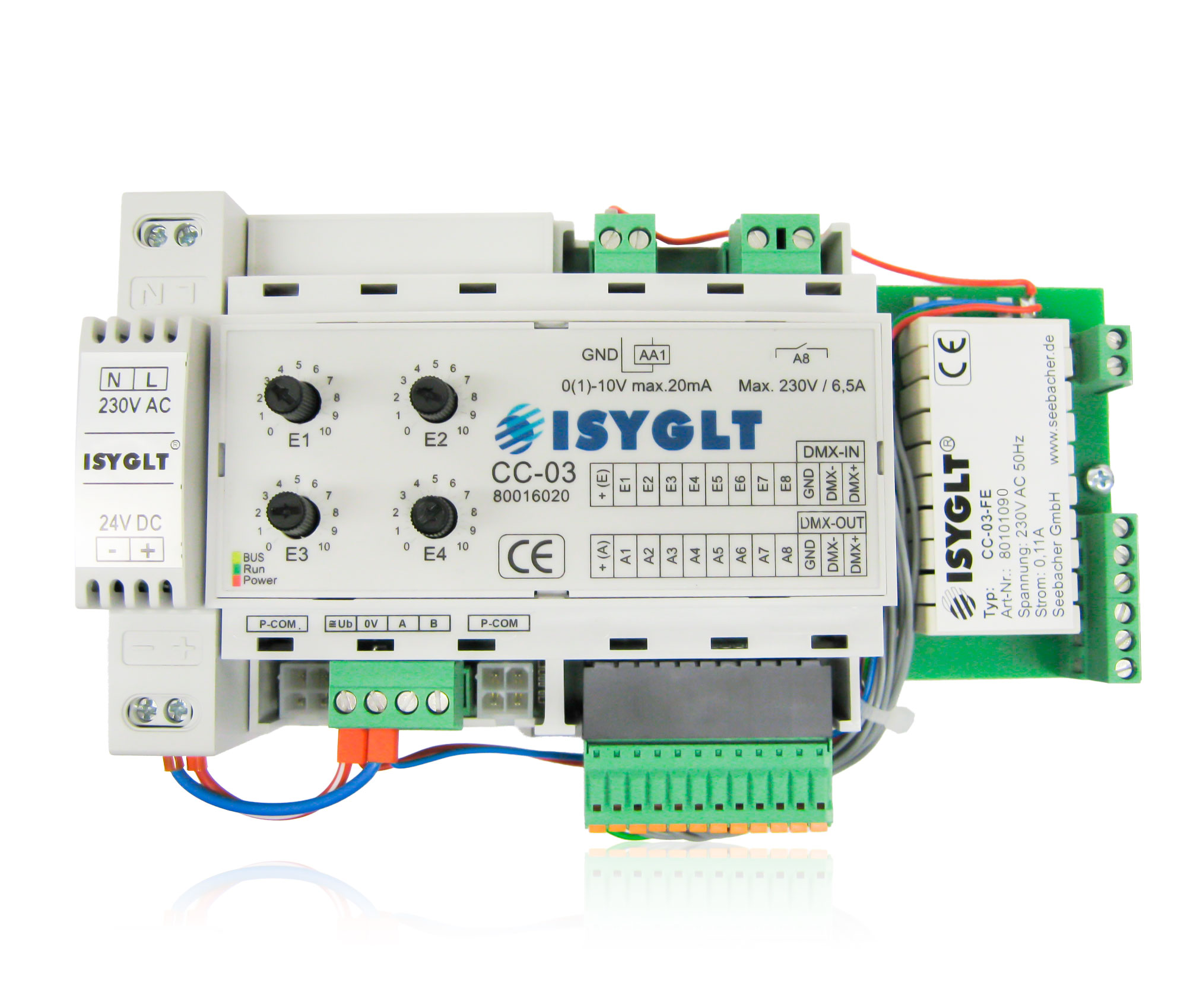
When power is applied, the light dims to 100% and the “Bright” function is activated. The “Bright,” “Dim,” and “Stop” buttons allow for individual brightness adjustment. The comfort of this control method lies in its hold function. Simply tapping “Bright” or “Dark” triggers an automatic dimming cycle in the respective direction. Pressing the “Stop” button maintains the current light level. Pressing the “DIA” button recalls the brightness value set on potentiometer 1 (“DIA Value”).
Potentiometer 2, “Fade Time,” allows you to set the fade time within a range of 0–30 seconds. The fade time is defined as the dimming time from 0 to 100%. A typical default value here is 5 seconds. Dimming using the function buttons always occurs at the set fade time. The analog value is output immediately when the light is turned on or off.
| Operating voltage | 230V AC |
| Current consumption | 110mA at 230V |
| Inputs (buttons) | Input decoupled via a 24V DC relay. |
| Outputs (feedback signals) | Outputs isolated via a 24V DC relay; total current: 300mA maximum |
| Relay output | 230V 1500VA (max. 6.5A) with triac zero voltage switch |
| Analog output | 1 analog channel 8 bit resolution 0-10V (1-10V) Output current max. 20mA (sink or source) |
| Connection | screw terminals 2.5mm² |
| Operating temperature | -10°C...+50°C |
| Storage temperature | -25°C...+70°C |
| Humidity | 0...85% r. h. non-condensing |
| Protection class | IP 30 |
| Design | DIN rail with mounting holes spaced according to FE (the power supply and print must be removed for mounting) |
| Dimensions | WxHxD 110x190x70mm |
| Weight | 435 g |
| Type designation | CC-03-FE |
| Article no. | 80101090 |
| Brand | |
| Compliance | CE |