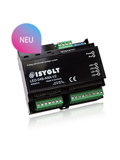
Analogue LED Dimmer - NON-PWM - with 4 independent constant current outputs, CC (constant current) 250mA to 1550mA. Dimming 0-100% high-resolution (19 bit), channels can be coupled to increase performance.
Quick Facts
- 4 dimming channels 250mA to 1550mA
- Higher currents possible by coupling the channels
- Dimming 0-100%, internal 19 Bit resolution
- Protocol ISYGLT, DMX512 8/16-Bit, DMX-RDM and DALI
- NON-PWM flicker-free dimming (amplitude/analogue dimming)
- Functions for emergency lighting, special lighting, panic lighting
The non-PWM LED dimmer was developed for absolutely flicker-free dimming of constant current-controlled LEDs or LED lights. The dimmer operates completely without pulse-width modulation and is a fully analog dimmer that covers the entire dimming range from 0% to 100% continuously. Unlike many other LED dimmers (drivers), which switch to PWM dimming in the lower range, this dimmer works purely analog throughout. It is possible to perfectly control the brightness of the LEDs between 0% and 100% with a dimming resolution of 19 bits (internal resolution). The LED dimmer can be set from speed calculation to absolute time calculation by parameterising each channel. This makes it easy to realise all conceivable control tasks.
Depending on the configuration and LED type, this dimmer can control LEDs with a total output of up to 300W (4x 75W).
Channel coupling is possible for LEDs with higher currents. When coupling, the physical outputs can be defined as main current and precision current. For the output with the precision current definition, we recommend calibrating a lower current (e.g. 300mA). This allows the dimmer to be dimmed up very sensitively from the lowest dimming range, especially for LEDs with high currents (e.g. 2500mA).
We recommend this dimmer for all areas and applications where perfect dimming down to the minimum and - thanks to analogue dimming - healthy and camera-compatible dimming of the lighting is important.
Application areas:
- Planetarium
- Theatre
- Museum, gallery, exhibition
- Clinic and nursing home
- Office and other workplaces
- School and educational institution
- Hotel and conference room
- Shopping mall and retail shop
The LED dimmer can be operated with either the ISYGLT, DMX512 8/16 bit, DMX-RDM 8/16 bit or DALI protocols.
The functions and options of the LED-04B-ANA-V2:
- Calculation of rise times from 0.5 seconds to 12 hours
- Independent moving from current ACTUAL values to preset SET values at a preset speed (optional in preset time)
- Protocols: ISYGLT, DMX 8-Bit, DMX-16B(L-H), DMX-16Bit(H-L), DMX-RDM, DALI-II, DT6 and DT8
- 19 bit analogue resolution – this corresponds to 524288 steps from 0-100%
- Standardised power definitions for all protocols
- Calibration function for current setting, minimum value calibration mode
- Channel coupling function with optional definition of a precision channel
- „Soft switch-off“ function
- Current limiting function for commissioning (e.g. if lights for the painter are still covered)
- Adaptation to different LED modules
- Complex emergency operation function
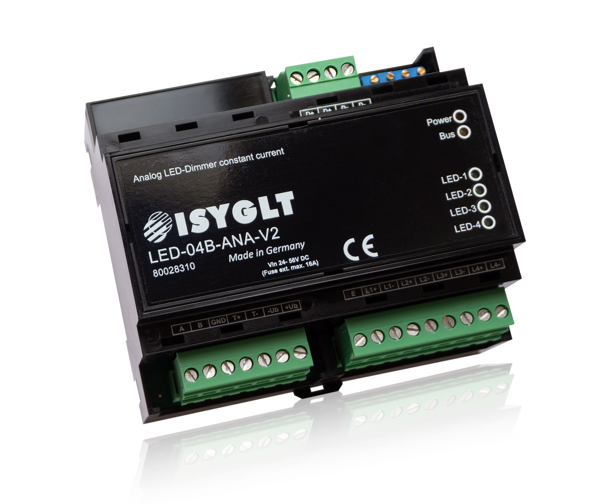
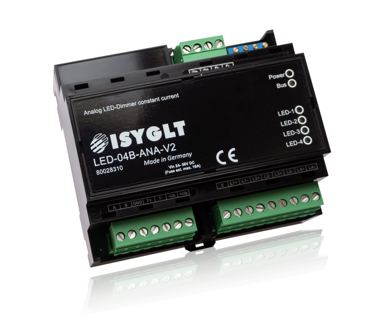
| Type designation | LED-04B-ANA-V2 |
| Article no. | 80028310 |
| Operating voltage | 24V to 56V DC for the supply of the LEDs depending on the type |
| Emergency operating input | 24V to 56V DC |
| LED forward voltage | 12V to 54V (depending on the voltage drop of the line); the LED forward voltage including the voltage drop of the line must be 2V lower than the supply voltage! |
| Mains fuse | max. 16A at Umax 56V DC |
| Current consumption | max. 1550mA per LED circuit |
| Outputs |
4 x constant current, channels can be coupled, separately adjustable at the factory with 250mA to 1550mA each (please specify the desired current value for each circuit when ordering) |
| Power loss |
Idle: 0.162W / channel Full load and worst conditions: 2.5W / channel |
| BUS control | ISYGLT / DMX512 8/16-Bit, DMX-RDM, DALI |
| Line length power supply to LED dimmer | max. 20m (for cross-section calculation of the line, observe max. permissible voltage drop) |
| Line length LED dimmer up to the last LED | max. 50m |
| Dimming resolution | 19 bit |
| Subnet (RS-485) | max. 5.6V limitation by Z-diodes |
| Connection | Screw terminals 2.5mm² |
| Operating temperature | -10°C to +45°C |
| Storage temperature | -25°C to +70°C |
| Humidity | 0...85 % r. h. non-condensing |
| Protection class | IP 20 |
| Design | DIN rail housing 6 HP |
| Dimensions | LxWxH 106x90x61mm |
| Weight | 250g |
| Brand | ISYGLT |
| Compliance | CE |


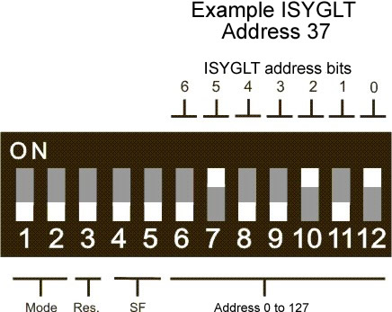
| Switch | Function | Description |
|---|---|---|
| DIP 1 | Protocol 1 | OFF |
| DIP 2 | Protocol 2 | OFF |
| DIP 3 | Channel setup | Power limitation for commissioning |
| DIP 4 | Channel setup | Minimum value calibration option |
| DIP 5 | Reserve | OFF |
| DIP 6 | Address bit 7 | Module address (highest bit) |
| DIP 7 | Address bit 6 | Module address |
| DIP 8 | Address bit 5 | Module address |
| DIP 9 | Address bit 4 | Module address |
| DIP 10 | Address bit 3 | Module address |
| DIP 11 | Address bit 2 | Module address |
| DIP 12 | Address bit 1 | Module address (lowest bit) |
DMX operation - The following functions can be set via parameter settings:
- 1, 2, 3, or 4-channel operation
- DMX 8-bit, 16-bit H,L, 16-bit L,H
- Fade time calculation absolute or speed
- Fade time (none, 10 ms, 20 ms ... up to 5 s)
- Dimming curves, zero point correction, end point correction
- Action in case of BUS failure
- Emergency operation
DMX = DIP 1 = ON, DIP 2 = OFF
| Switch | Function | Description |
|---|---|---|
| DIP 1 | Protocol 1 | ON |
| DIP 2 | Protocol 2 | OFF |
| DIP 3 | Channel setup | Power limitation for commissioning |
| DIP 4 | Address bit 9 | DMX start address (highest bit) |
| DIP 5 | Address bit 8 | DMX start address |
| DIP 6 | Address bit 7 | DMX start address |
| DIP 7 | Address bit 6 | DMX start address |
| DIP 8 | Address bit 5 | DMX start address |
| DIP 9 | Address bit 4 | DMX start address |
| DIP 10 | Address bit 3 | DMX start address |
| DIP 11 | Address bit 2 | DMX start address |
| DIP 12 | Address bit 1 | DMX start address (lowest bit) |
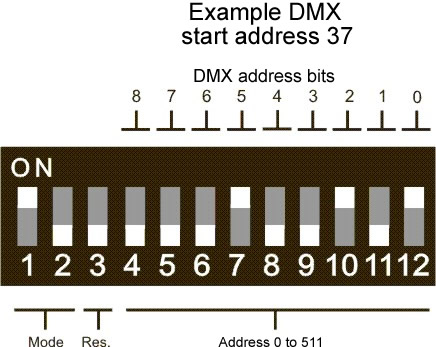
Example: DMX address setting
| DIP switch | Output | |
|---|---|---|
| Address 0 | 10x000000000 | DMX-RDM operation |
| Address 1 | 10x000000001 | DMX channel 1, 2, 3 and 4 (at 4-channel 8 bit) |
| Address 10 | 10x000001010 | DMX channel 10, 11, 12 and 13 (at 4-channel 8 bit) |
| Address 127 | 10x001111111 | DMX channel 127, 128, 129 and 130 (at 4-channel 8 bit) |
| Address 509 | 10x111111101 | DMX channel 509, 510, 511 and 512 (at 4-channel 8 bit) |
DALI operation
| Switch | Function | Description |
|---|---|---|
| DIP 1 | Protocol 1 | OFF |
| DIP 2 | Protocol 2 | ON |
| DIP 3 | Channel setup | Power limitation for commissioning |
| DIP 4 | Address bit 9 | Reserve |
| DIP 5 | Address bit 8 | Reserve |
| DIP 6 | Address bit 7 | Reserve |
| DIP 7 | Address bit 6 | Reserve |
| DIP 8 | Address bit 5 | Reserve |
| DIP 9 | Address bit 4 | Reserve |
| DIP 10 | Address bit 3 | Reserve |
| DIP 11 | Address bit 2 | Reserve |
| DIP 12 | Address bit 1 | Reserve |
Function Indicators (LEDs on the Module)
| LED | Designation | State | Meaning |
|---|---|---|---|
| red | POWER | Off | No operating voltage |
| On | Operating voltage, no error | ||
| Blinking | Signals a parameter error | ||
| yellow | BUS | Off | Error BUS wiring |
| On | Error BUS communication (address not detected) | ||
| Blinking | Interference-free data transmission via the BUS line | ||
| 4x green | LED 1-4 | Dimming | Signals the intensity of the corresponding output |
Variants
| LED-04ECM-DMX-200 Article no. 80028346, 4-channel LED dimmer for power LED (200mA) with colourfast dimming and colour temperature control |
| LED-04ECM-DMX-350 Article no. 80028042, 4-channel LED dimmer for power LED (350mA) with colourfast dimming and colour temperature control |
| LED-04ECM-DMX-500 Article no. 80028049, 4-channel LED dimmer for power LED (500mA) with colourfast dimming and colour temperature control |
| LED-04ECM-DMX-700 Article no. 80028047, 4-channel LED dimmer for power LED (700mA) with colourfast dimming and colour temperature control |
| LED-03EC-DMX-350-V2 Art. no. 80028051, 3-channel LED dimmer for power LED (350mA) with colourfast dimming, with housing, for very noise-sensitive applications |
| LED-02E-DMX16-700-V2 Article no. 80028380, 2-channel LED dimmer for power LED (700mA), with housing, for very noise-sensitive applications, 2nd protocol DMX512-16Bit |
| LED-03EC-DMX-700-V2 Art. no. 80028070, 3-channel LED dimmer for power LED (700mA) with colourfast dimming, with housing, for very noise-sensitive applications |
| LED-02E-DMX-1000 Article no. 80100316, 2-channel LED dimmer for power LED (1000mA), with housing |
| LED-04B-ANA-DMX Article no. 80028304, 4-channel non-PWM analog LED dimmer for power LED (250mA-1550mA), in DIN rail mounted housing |