The non-PWM LED Dimmer was developed for absolutely flicker and flicker-free dimming of constant current controlled LEDs or LED lights. It dims absolutely without pulse width modulation and is a purely linear dimmer. It is possible to perfectly control the brightness of the LEDs between 0% and 100% with a dimming resolution of 16 bit (internal resolution in ISYGLT operation). The minimum brightness of the LED Dimmer per channel can be adjusted on the device and thus optimally adapted to the LEDs to be controlled.
Depending on configuration and LED type, this dimmer can control LEDs with a total of 300W (4x 75W) power.
Recommended areas of use are all areas in which healthy lighting is ensured, as the effects of conventional PWM dimming have not been fully investigated, but are classified by experts as posing a health risk. PWM is used as standard in all previous LED Dimmers, including the DALI and KNX/EIB standards. Therefore, the use of non-PWM dimming is particularly recommended in areas where people stay longer or where high demands are placed on lighting quality:
- planetarium
- theater
- museum, gallery, exhibition
- clinic and nursing home
- office and other workplaces
- school and educational institution
- hotel and conference room
- shopping centre and shop
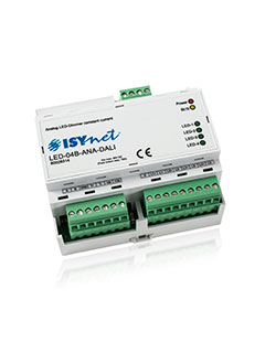
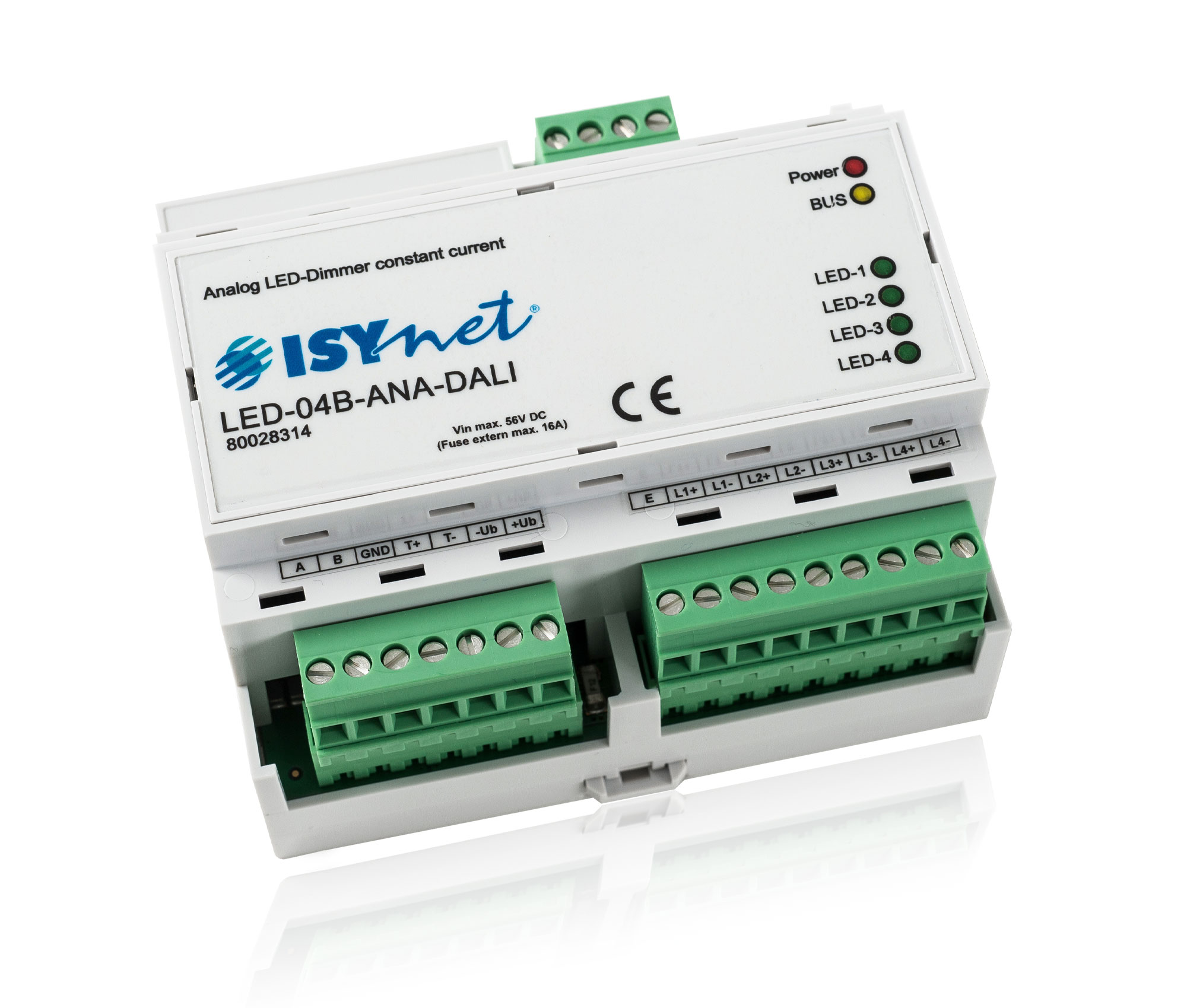
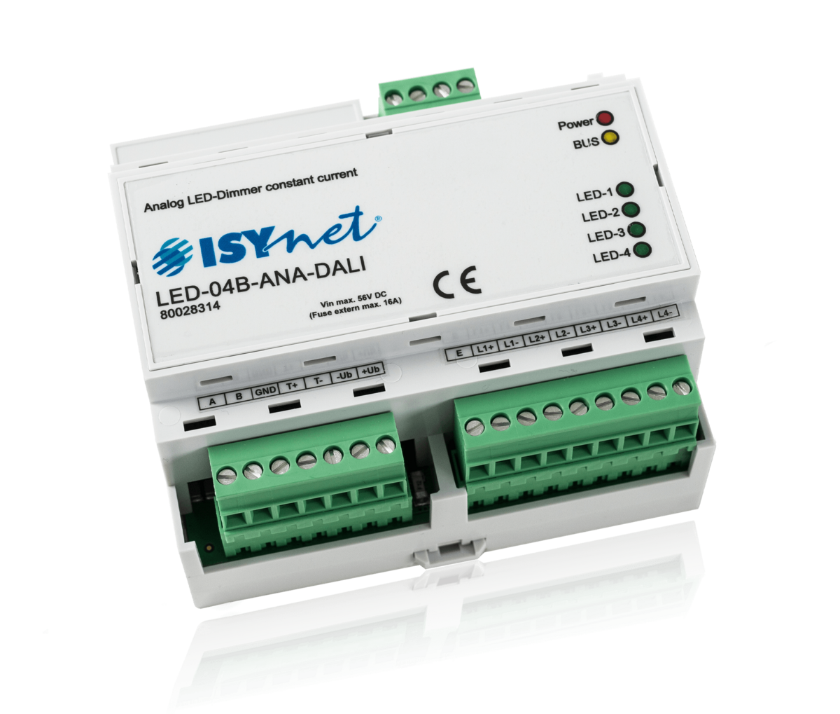
The LED-04B-ANA-DALI is controlled via the standard DALI protocol.
| Type designation | LED-04B-ANA-DALI |
| Article no. | 80028314 |
| Operating voltage | 24V to 56V for the supply of the LEDs depending on the type |
| Emergency operation input | 24V to 56V DC |
| LED forward voltage | 12V to 54V (depending on the voltage drop of the line); the LED forward voltage including the voltage drop of the line must be 2V lower than the supply voltage! |
| Mains fuse | max. 16A at Umax 56V DC |
| Current consumption | max. 1550mA per LED circuit |
| Output | 4 x constant current, separately adjustable in the factory with 250mA to 1550mA each for power LEDs (please specify the desired current value for each circuit when ordering) |
| Power dissipation | idle circuit: 0.162W / channel, full load and worst conditions: 2.5W / channel |
| Control |
DALI compatible to DALI IEC 62386-102 4 DALI Standard CONTROL GEARS (DEVICE TYPE 0) PHYSICAL MIN LEVEL = 1 Exceptions: - no lamp failure detection - no SYSTEMFAILURE LEVEL "255" only "0-254" |
|
Cable length power supply to LED dimmer |
max. 20m |
| Cable length LED dimmer up to the last LED | max. 50m per channel |
| Dimming resolution | 16 bit |
| Subnet (RS-485) | max. 5.6V limitation by Z-diodes |
| Mounting | DIN rail-mounting on 35mm DIN rail |
| Connection | pluggable screw terminals 2.5mm² |
| Max. ambient temperature | -10°C to +40°C (non-condensing) |
| Storage temperature | -25°C to +70°C |
| Humidity | 0...85 % r. h. non-condensing |
| Protection | in not installed state IP 20 |
| Design | Plastic housing light grey, snap-on on 35mm DIN rail 6 HP |
| Dimensions | WxHxD 106x90x59mm DIN rail-mounting (6 HP) |
| Weight | 250g |
| Brand | ISYnet |
| Compliance | CE |


DIP switches - control GEARS definition
| DIP-1 | DIP-2 | Outputs | DALI-GEAR |
|---|---|---|---|
| OFF | OFF | Cathode 1 (L1) | GEAR A |
| Cathode 2 (L2) | GEAR B | ||
| Cathode 3 (L3) | GEAR C | ||
| Cathode 4 (L4) | GEAR D | ||
| ON | OFF | Cathode 1 (L1) | GEAR A |
| Cathode 2 (L2) | GEAR A | ||
| Cathode 3 (L3) | GEAR A | ||
| Cathode 4 (L4) | GEAR A | ||
| OFF | ON | Cathode 1 (L1) | GEAR A |
| Cathode 2 (L2) | GEAR A | ||
| Cathode 3 (L3) | GEAR B | ||
| Cathode 4 (L4) | GEAR B | ||
| ON | ON | Cathode 1 (L1) | GEAR A |
| Cathode 2 (L2) | GEAR B | ||
| Cathode 3 (L3) | GEAR C | ||
| Cathode 4 (L4) | GEAR C | ||
| Notice: After changing the DIP switches, the DALI addresses of the LED dimmer must be deleted again. This must then be reparameterized in the current configuration. | |||

Set minimum dimming values
A potentiometer and a button are available for setting the minimum dimming values.
The dimming channels must be active before setting - dimming values >= #1
DIP switches 9-12 are used to select the channels to be set (see table below). The setting can be made separately for each channel or for several channels at the same time.
As soon as one or more DIP switches are set to ON, the relevant channels are set to DALI dimming value #1 and the potentiometer value is output. The minimum value threshold can be adjusted by turning the potentiometer. The potentiometer is updated every 0.5 seconds.
If the "S2" key is pressed for longer than 3 seconds, the current minimum value is saved. This is indicated by 3 blinks of the yellow LED.

DIP switches - setting min values of the channels
| DIP-1 | DIP-2 | Outputs | DALI-GEAR | DIP-9 | DIP-10 | DIP-11 | DIP-12 |
|---|---|---|---|---|---|---|---|
| OFF | OFF | Cathode 1 (L1) | GEAR A | ON | |||
| Cathode 2 (L2) | GEAR B | ON | |||||
| Cathode 3 (L3) | GEAR C | ON | |||||
| Cathode 4 (L4) | GEAR D | ON | |||||
| ON | OFF | Cathode 1 (L1) | GEAR A | ON | |||
| Cathode 2 (L2) | GEAR A | ON | |||||
| Cathode 3 (L3) | GEAR A | ON | |||||
| Cathode 4 (L4) | GEAR A | ON | |||||
| OFF | ON | Cathode 1 (L1) | GEAR A | ON | |||
| Cathode 2 (L2) | GEAR A | ON | |||||
| Cathode 3 (L3) | GEAR B | ON | |||||
| Cathode 4 (L4) | GEAR B | ON | |||||
| ON | ON | Cathode 1 (L1) | GEAR A | ON | |||
| Cathode 2 (L2) | GEAR B | ON | |||||
| Cathode 3 (L3) | GEAR C | ON | |||||
| Cathode 4 (L4) | GEAR C | ON | |||||
| Notice: If channel interconnections are active ("CONTROL GEARS"), the setting is always the same for the group. Only LEDs with the same characteristics can be calibrated in this way. | |||||||

Additional Equipment
| Article no.: 80100604 ISYnet - NT-LED-12V-15A Power Supply for LED applications |
| Article no.: 80100608 ISYnet - NT-LED-48V-5A Power Supply for LED applications |
| Article no.: 80100609 ISYnet - NT-LED-48V-5,4A Power Supply for LED applications |
| Article no.: 80100610 ISYnet - NT-LED-48V-10A Power Supply for LED applications |
| Article no.: 80100611 ISYnet - NT-LED-48V-20A Power Supply for LED applications |
| Article no.: 80100616 ISYnet - NT-LED-24V-5A Power Supply for LED applications |
| Article no.: 80100618 ISYnet - NT-LED-24V-10A Power Supply for LED applications |
| Article no.: 80100619 ISYnet - NT-LED-24V-10A Power Supply for LED applications |
| Article no.: 80100620 ISYnet - NT-LED-24V-20A Power Supply for LED applications |
| Article no.: 80100640 ISYnet - NT24V/40A-3Ph Power Supply for LED applications |
| Article no.: 80100641 ISYnet - NT-LED-24V-40A Power Supply for LED applications |