
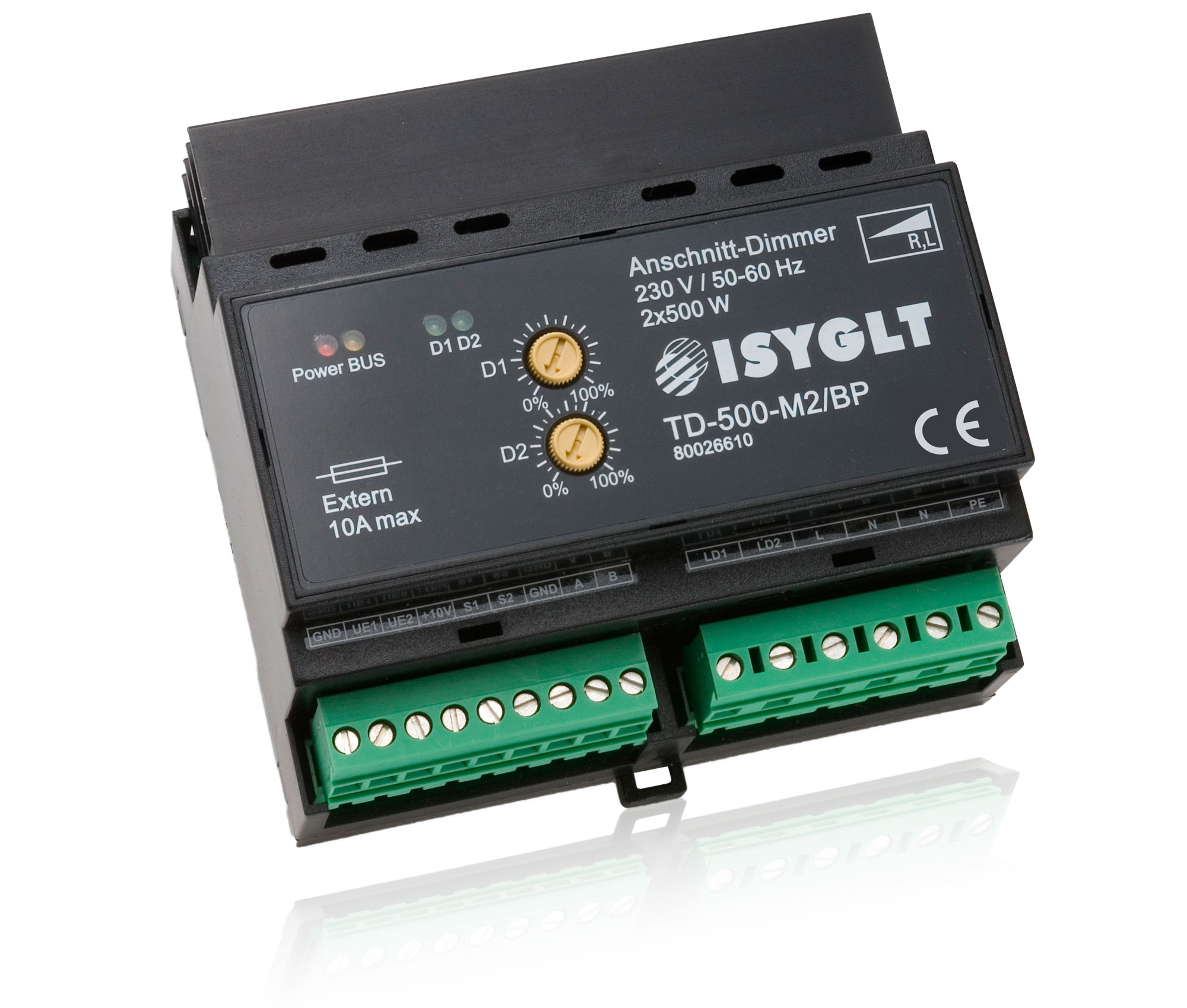
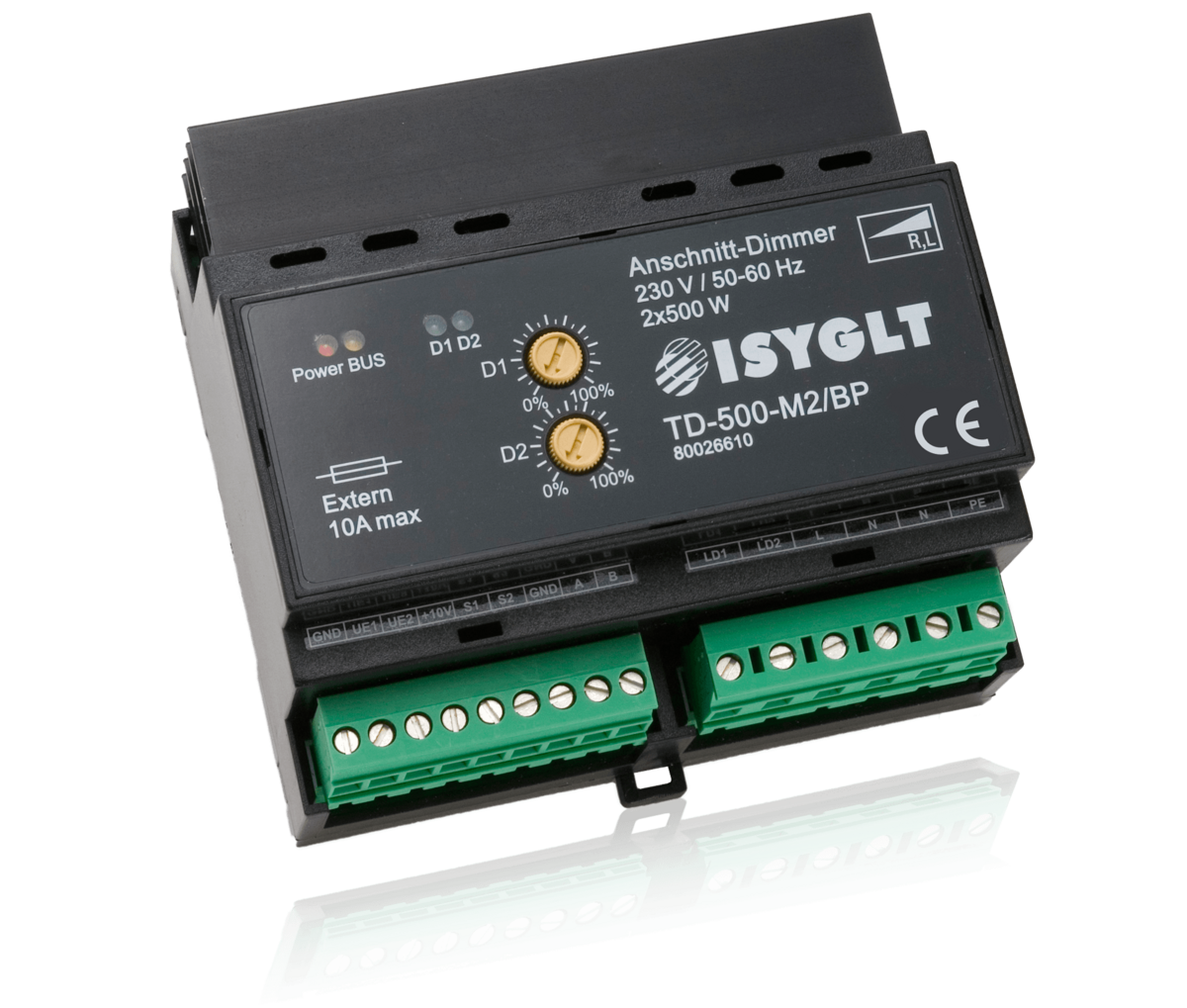
The thyristor dimmer is a classic Leading Edge Dimmer in 16Bit "Thyristor Antiparallel Technology". This type of control is certainly the upper class of dimmers and cannot be compared to the simpler triac dimmers. The control and monitoring for each half-wave is carried out separately here, since a thyristor is available and responsible accordingly. The dimmer is characterised by its extreme robustness in the respective power class. In leading edge technology, all ohmic loads (incandescent lamps, high-voltage halogen lamps, heaters) and inductive loads (halogen with magnetic transformers, fluorescent lamps with VIP-90, motors, plastic welding equipment with magnetic transformers) can be operated. The dimmer has several control modes and can be operated conventionally with potentiometer, button, 0-10V or 1-10V signal or digitally in ISYGLT-BUS, DMX512 8-Bit or DMX512 16-Bit. The basic function parameters are set via 2 DIP switches; detailed parameters can only be set in the ISYGLT system.
| Type designation | TD-500-M2/BP |
| Article no. | 80026610 |
| Mains supply | 230V / 45 to 65 Hz |
| Mains fuse | 1 x 230V automaton B6A or B10A |
| Output | 2 x 230V leading edge 35W to 500W per channel |
| Power loss |
<2 ... 13W (Stand-by ... full load) !! Please ensure sufficient ventilation of the switch cabinet or housing! |
| 1 (0)-10V |
sink current at 1-10V = 1mA source current with hardware option 0-10V = 0.5mA at 20kOhm |
| Insulation voltage | 3500V (ISYGLT-BUS / mains) |
| Overtemperature protection |
temperature fuse (bimetal) 105°C +/-5K self-resetting in the primary circuit of the dimmer (contact rating 10A at Cos-Phi=1; 6.3A at Cos-Phi=0.6) |
| Subnet (RS-485) | max. 5.6V limitation by Z diodes |
| Connection | screw terminals 1.5mm² pluggable |
| Operating temperature |
-10...+45°C > at +50°C max. 60% connectable power > at +55°C max. 50% connectable power > at +60°C max. 30% connectable power |
| Storage temperature | -25...+70 °C |
| Humidity | 0...85 % r.h. non-condensing |
| Protection class | IP 30 |
| Protection class | I |
| Design | DIN rail housing |
| Dimensions | WxHxD 106x90x59mm rail-mounted device (6 HP) |
| Weight | 410 g |
| Brand | ISYGLT |
| Compliance | CE |


| OFF | DIP top | ON | |
|---|---|---|---|
| All OFF | OFF | 1 | |
| OFF | 2 | ||
| OFF | 3 | ||
| OFF | 4 | ||
| OFF | 5 | ||
| OFF | 6 | ||
| OFF | 7 | ||
| OFF | 8 |
| OFF | DIP below | ON | |
|---|---|---|---|
| Mode | OFF | 1 | |
| Mode | 2 | Stand-alone | |
| OFF | 3 | Speedalaising (Oversampling) ON | |
| U-inputs 0-10V | 4 | U-inputs 1-10V | |
| Linear dimming curve | 5 | Visor dimming curve | |
| Function off | 6 | Min dimming level | |
| Curve linear | 7 | Min dimming level | |
| Mode Analog inputs | 8 | Mode 1-Button dimmer |

| DMX address bits | 1 | Address bit 7 | |
| 2 | Address bit 6 | ||
| 3 | Address bit 5 | ||
| 4 | Address bit 4 | ||
| 5 | Address bit 6 | ||
| 6 | Address bit 2 | ||
| 7 | Address bit 1 | ||
| 8 | Address bit 0 |
| Mode | 1 | ON = DMX512 | |
| Mode | 2 | ON + 1 ON = DMX512-16Bit | |
| OFF OFF | 3 | Speedalaising (Oversampling) ON | |
| U-inputs 0-10V | 4 | U-inputs 1-10V | |
| Linear dimming curve | 5 | Visor dimming curve | |
| Function off | 6 | Min dimming level | |
| Curve linear | 7 | Min dimming level | |
| DMX address bits | 8 | Address bit 8 |
Function Indicators (LEDs on the Module)
| LED | Designation | State | Meaning |
|---|---|---|---|
| red | Power | OFF | No operating voltage |
| ON | Operating voltage, no error | ||
| yellow | BUS | OFF | No BUS signal detected |
| ON | BUS signal detected, own address not detected | ||
| Even blinking | BUS signal and own module address detected | ||
| green | State of dimmer outputs | OFF | Output "OFF" no error |
| ON | Output "ON" no error |
9-pole connector left
| GND | Reference potential (ground) for the voltage inputs (0-10V) and BUS RS485 (internally connected with the seventh terminal) |
| UE1 | Control voltage input for the dimmer output LD1 (emergency function) |
| UE2 | Control voltage input for the dimmer output LD2 (emergency function) |
| +10V | 10V for the connection of an external potentiometer |
| S1 | Voltage channel 1 for sink current 1-10V (insert bridge to "UE1") |
| S2 | Voltage channel 2 for sink current 1-10V (insert bridge to "UE2") |
| GND | Reference potential (ground) for the voltage inputs (0-10V) and BUS RS485 (internally connected with the first terminal) |
| A | Subnet (BUS A, RS-485) |
| B | Subnet (BUS B, RS-485) |
Variants
Higher power Leading Edge Dimmer
Universal Dimmer UD-700-X2 - especially for LED light sources
Leading Edge, Trailing Edge and Universal Dimmers can also be found in the catalog.
Anfrage
TD-500-M2/BP
Article no.: 80026610-S